1. Interrupt
Related reference articles:
RISC-V teaching plan
The concept of interruption was introduced in RISC-V C language programming 2 (3) Interrupt and Interrupt Engineering. Here I will review it again. Interrupt refers to the interruption of the currently running program by the CPU due to internal/external events when the CPU is running the program normally. And go to the service program for internal/external events, when the service is completed, it returns to the normal program to execute the CPU .
From mcause (machine trap cause), the machine mode exception cause register can know the reason for the interrupt, see Figure 1. As can be seen from the figure, there are three main types of interrupts, software interrupts, timer interrupts, and external interrupts. Three kinds of interrupts can occur in three different modes: user mode, monitor mode, and machine mode, only interrupts in machine mode are discussed here.

Figure 1 Description of the mcause register in the v1.9 privileged architecture [1]
RISC-V defines the following interrupts:
- Software , architecture-defined software interrupts
- Timer , an architecture-defined timer interrupt
- External , peripheral interrupt, or external interrupt
- (Optional) Local, a specific peripheral interrupt, not discussed in detail here
There are two more concepts related to handling interrupts:
- CLINT (core-local interrupt controller), the local core interrupt controller
- local interrupt (local interrupt), only supports standard software interrupts and timer interrupts
- It was introduced in RISC-V C language programming 2 (3) Interrupt and Interrupt Engineering
- PLIC (platform-level interrupt controller), platform-level interrupt controller
- global interrupt (global interrupt), supports all types, such as UART, GPIO, PWM, etc.
- Receive interrupt signals from peripheral devices and arbitrate to process these signals according to priority
- Here we mainly introduce the design and implementation of PLIC
2. PLIC architecture design
- 127 external interrupt sources (interrupt IDs), including SPI, I2C, PWM, etc., see the address map (click here ) for details, as shown in Figure 2.
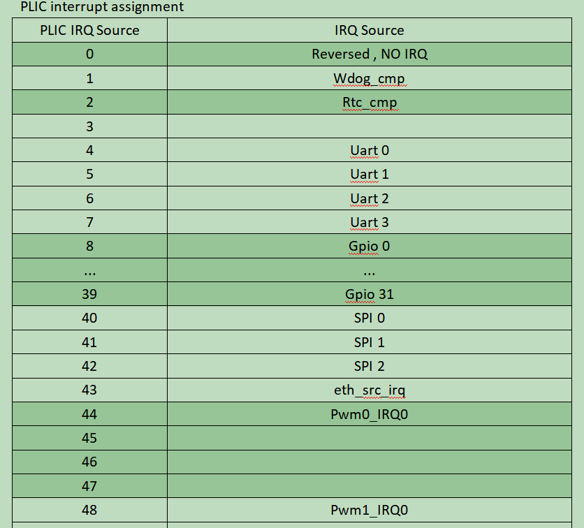
Figure 2 Interrupt ID
- A total of 7 software programmable interrupt priority levels (priority level)
Interrupt priority level 0 is reserved for “never interrupt”, interrupt priority levels 1-7 are valid interrupt priorities, and the priority increases accordingly. If there are two interrupt sources with the same priority during interrupt arbitration, the interrupt source with the smaller interrupt ID is executed first. Setting the interrupt priority is determined by the lowest three bits of the corresponding register, as shown in Figure 3, the priority range is 0-7, 7 corresponds to the highest priority, and 0 corresponds to the lowest priority.
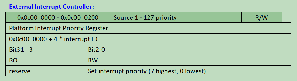
Figure 3 Interrupt priority setting
- Interrupt ID 0 is called “no interrupt”, so actually interrupt ID 1 is the first global interrupt, see Figure 2, Interrupt ID for details.
- The interrupt pending bit is implemented by 4 full-byte registers (4 x 32 = 128), corresponding to 128 interrupt sources. Bit 0 of the first byte is hardwired to 0, representing the non-existent interrupt ID 0. The Interrupt Pending Register is read-only.
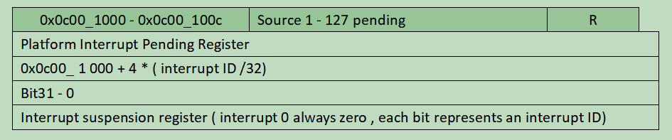
Figure 4 Interrupt suspension settings
- The interrupt enable bit (interrupt enable bit) is similar to the interrupt suspension bit. Each bit corresponds to an interrupt source, which is implemented by 4 full-byte registers and is a read-only register.
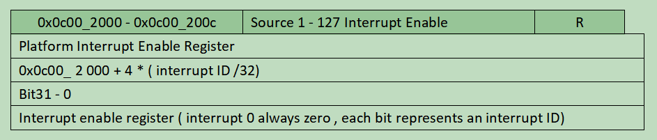
Figure 5 Interrupt Enable Register
- Interrupt priority thresholds (priority thresholds) consist of seven levels. External interrupts with a priority less than or equal to the priority threshold are masked. Use only the lowest three bits of the corresponding register to determine the threshold/threshold. Example: Priority threshold 0 allows all external interrupts of priority (1~7) except 0; priority threshold 7 will block all external interrupts.
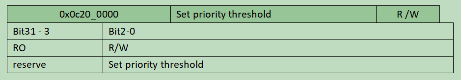
Figure 6 Interrupt Priority Threshold/Threshold Register
- Interrupt claim, returns the ID of the pending interrupt with the highest priority, or 0 if no interrupt is pending. After the declaration is completed, the corresponding interrupt pending bit will be automatically cleared. Interrupt declarations are not interfered with by interrupt priority threshold settings. Note: Here the interrupt declaration and interrupt completion are completed by the read and write of the same register.
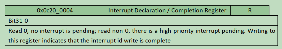
Figure 7 Interrupt Declaration/Completion Register
- Interrupt completion (interrupt completion), after completing the interrupt handler (interrupt handler), write the corresponding interrupt ID received at the time of the interrupt declaration.
3. Article reference
[1] Riscv.org , 2021. [Online]. Available: https://riscv.org/wp-content/uploads/2019/12/riscv-spec-20191213.pdf. [Accessed: 22- Feb- 2021] .
