1.Introduction to Interrupt
Direct to Table of Contents:
RISC-V Syllabus
Before diving into the project, a simple introduction of interrupt should be mentioned. In digital computers, interrupts are the processor’s response to events that require software attention. The interrupt condition will warn the processor and use it as a request to the processor to interrupt the currently executing code when allowed so that the event can be processed in time. If the request is accepted, the processor will respond by suspending its current activity, saving its state, and executing a function called an interrupt handler (or interrupt service routine, ISR) to handle the event. The interrupt is temporary, and unless the interrupt indicates a fatal error, the processor will resume normal activity after the interrupt handler completes [1].
More complicatedly, processors may face the situation to handle multiple interrupts. In that case, interrupt priority level (IPL) should be considered. Usually, only one interrupt is allowed at one time, other interrupts shall wait until it completes. Sometimes, interrupts may occur during the interrupt handling, it is called nested interrupt.
2.RISCV_timer_irq Project
RISCV_timer_irq avoids complicated interrupt occurrence. Machine timer interrupt is implemented here.
Import the project as the same steps with the previous projects(Clink here for more information on creating a new C project in Freedom Studio). The corresponding Freedom Studio project explorer is shown in Figure 1.
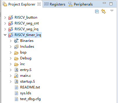
Figure 1 RISCV_timer_irq
A new header file fii_irq.h is used here. Except for that, entry.S and main.c will be introduced as well. The rest of the header files are the same as the previous projects.
- Fii_irq.h
#ifndef __FII_IRQ_H
#define __FII_IRQ_H

    #ifdef __cplusplus
     extern "C" {
    #endif

    #include "fii_types.h"
    #include "encoding.h"

    #define CLINT_CTRL_ADDR (0x02000000)     //define kernel interrupt base address
    #define PLIC_CTRL_ADDR  (0x0C000000)     //define external interrupt base address
    #define TIME_ADDR       CLINT_CTRL_ADDR  //timer interrupt address
    #define RTC_FREQ        32768            //RTC timer frequency
    #define MCAUSE_INT      0x80000000       //mcause bit 31 mask, decision making, '1' is interrupt, '0' is exception
    #define MCAUSE_CAUSE    0x7FFFFFFF       //mcause bit 30-0 mask, decision making, exception code
                                             //here, machine timer interrupt exception code is '7'

    //offset with respect to the kernel interrupt base address
    #define CLINT_CTRL_REG  (0x0000 << 2)       //0x0000, timer register
    #define TM_CTRL_REG     (0x0001 << 2)       //0x0004, timer control register
    #define TM_L_REG        (0x0002 << 2)       //0x0008, timer_val register lower 32 bits
    #define TM_H_REG        (0x0003 << 2)       //0x000c, timer_val register higher 32 bits
    #define TMCMP_L_REG     (0x0004 << 2)       //0x0010, timer cmp register lower 32 bits
    #define TMCMP_H_REG     (0x0005 << 2)       //0x0014, timer cmp register higher 32 bits

    unsigned int handle_trap(unsigned int mcause, unsigned int epc);//define interrupt entrance function

    #ifdef __cplusplus
    }

    #endif

#endif  // __FII_IRQ_H
It should be mentioned that the implementation of mcause register is following the definition in version 1.9 “RISC-V instruction set manual privileged architecture”. As shown in Figure 2.
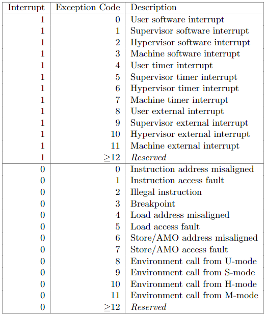
Figure 2 mcause register (bit 31= interrupt, bit 30-0 =exception code)
The interrupt project will use entry.S file, which is used for invoking the interrupt entrance function. In the initialization function of the main program, the address of trap_entry will be assigned to the RISCV CPU control and status register (CSR) mtvec. When the interrupt actually happens, the RISCV CPU program counter (PC) will suspend from the main execution, and points to the address of trap_entry function instead. After the interrupt handler completes, PC resumes the main execution.
- Entry.S
.equ REGBYTES,  (1 << 2)            #define REGBYTES to be 4

#.file "encoding.h"
  .section      .text.entry         #define it to be the code
  .align 2                          #2^2 = 4 bytes aligned
  .global trap_entry                #declaration of global function

trap_entry:                         #function actual starting point

  ADDI sp, sp, -32*REGBYTES         # REGBYTES = 4 #free stack depth to store
                                    #store x1-x31 register value to the stack

  SW x1, 1*REGBYTES(sp)
  SW x2, 2*REGBYTES(sp)
  SW x3, 3*REGBYTES(sp)
  SW x4, 4*REGBYTES(sp)
  SW x5, 5*REGBYTES(sp)
  SW x6, 6*REGBYTES(sp)
  SW x7, 7*REGBYTES(sp)
  SW x8, 8*REGBYTES(sp)
  SW x9, 9*REGBYTES(sp)
  SW x10, 10*REGBYTES(sp)
  SW x11, 11*REGBYTES(sp)
  SW x12, 12*REGBYTES(sp)
  SW x13, 13*REGBYTES(sp)
  SW x14, 14*REGBYTES(sp)
  SW x15, 15*REGBYTES(sp)
  SW x16, 16*REGBYTES(sp)
  SW x17, 17*REGBYTES(sp)
  SW x18, 18*REGBYTES(sp)
  SW x19, 19*REGBYTES(sp)
  SW x20, 20*REGBYTES(sp)
  SW x21, 21*REGBYTES(sp)
  SW x22, 22*REGBYTES(sp)
  SW x23, 23*REGBYTES(sp)
  SW x24, 24*REGBYTES(sp)
  SW x25, 25*REGBYTES(sp)
  SW x26, 26*REGBYTES(sp)
  SW x27, 27*REGBYTES(sp)
  SW x28, 28*REGBYTES(sp)
  SW x29, 29*REGBYTES(sp)
  SW x30, 30*REGBYTES(sp)
  SW x31, 31*REGBYTES(sp)

                   #pass the arguments before (input a0, a1, a2) and after (return a0) calling function handle_trap

  csrr a0, mcause      #x[a0] = CSRs[mcause]
  csrr a1, mepc        #x[a1] = CSRs[mepc]
  mv a2, sp            #x[a2] = x[sp]

  call handle_trap#invoke handle_trap function
  csrw mepc, a0        #CSRs[mepc] = x[a0]
                       #load x1-x31 register value from stack

  LW x1, 1*REGBYTES(sp)
  LW x2, 2*REGBYTES(sp)
  LW x3, 3*REGBYTES(sp)
  LW x4, 4*REGBYTES(sp)
  LW x5, 5*REGBYTES(sp)
  LW x6, 6*REGBYTES(sp)
  LW x7, 7*REGBYTES(sp)
  LW x8, 8*REGBYTES(sp)
  LW x9, 9*REGBYTES(sp)
  LW x10, 10*REGBYTES(sp)
  LW x11, 11*REGBYTES(sp)
  LW x12, 12*REGBYTES(sp)
  LW x13, 13*REGBYTES(sp)
  LW x14, 14*REGBYTES(sp)
  LW x15, 15*REGBYTES(sp)
  LW x16, 16*REGBYTES(sp)
  LW x17, 17*REGBYTES(sp)
  LW x18, 18*REGBYTES(sp)
  LW x19, 19*REGBYTES(sp)
  LW x20, 20*REGBYTES(sp)
  LW x21, 21*REGBYTES(sp)
  LW x22, 22*REGBYTES(sp)
  LW x23, 23*REGBYTES(sp)
  LW x24, 24*REGBYTES(sp)
  LW x25, 25*REGBYTES(sp)
  LW x26, 26*REGBYTES(sp)
  LW x27, 27*REGBYTES(sp)
  LW x28, 28*REGBYTES(sp)
  LW x29, 29*REGBYTES(sp)
  LW x30, 30*REGBYTES(sp)
  LW x31, 31*REGBYTES(sp)

  addi sp, sp, 32*REGBYTES     #return the stack pointer to the original location

  mret                         #resume the pc

.weak handle_trap

handle_trap:

1:
  j 1b
As shown in Figure 3, the principle of stack used above is as follows:
1: the location of the stack pointer before the interrupt
2: just before entering the interrupt, the stack pointer is moved to -32 x 4 bytes location
3: store 31 registers value between 1-2, and the stack pointer stays at location 2
4: before the interrupt finishes, load the data between 3 and 4 back to the 31 registers, and move the stack pointer back to 4.
Note that after the whole procedure, the stack pointer returns to its origin location. Although the stack leaves space for all 32 registers, x0 is hardwired to 0, the value is not changing, so only 31 registers will be operated.
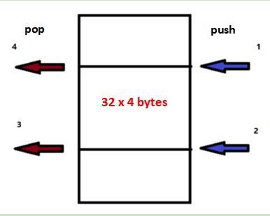
Figure 3 Stack principle
- Main.c
#include <stdio.h>               //include the standard I/O library, mainly used to declare printf function
#include "platform.h"            //user defined function in C library, including GPIO configuration, definition of the memory,
                                 //and related subfunctions and parameters

extern void trap_entry();        //declaration that trap_entry function is invoked from outside (entry.S)

void set_timer(u64_t msec)       //define a function to set timer
{
    //define 64 bits timers using 2*32 bits registers
    u64_t now;              //define 64 bits timer value 'now'

    now   = TIME_REG(TM_H_REG);           //fill the high 32-bits
    now   = now << 32;        //move the high 32-bits into the right place
    now   |= TIME_REG(TM_L_REG);           //bitwise or with the lower 32 bits

    //add time on the current timer, in milisec (msec), to get the 64 bits new timer 'then'
    u64_t then = now + msec*(RTC_FREQ/1000);         //conversion from RTC_FREQ (32768) to msec (1000)

    //write 'then' timer low 32 bits into timer compare register low 32 bits
    TIME_REG( TMCMP_L_REG ) = then & 0xffffffff;
    TIME_REG( TMCMP_H_REG ) = then >> 32;          //write 'then' timer high 32 bits into timer compare register high 32 bits

    return;
}

//timer counter

unsigned int time_cnt = 0;

/*Entry Point for Machine Timer Interrupt Handler*/
void handle_m_time_interrupt(){
    clear_csr(mie, MIP_MTIP);        //mie bit 7 is machine mode timer interrupt enable
                                     // clear MIP_MTIP bit right after entering the interrupt handler
                                     //prevent the nested interrupt
    set_timer(250);                  // reset the timer for 250ms

    // read the current value of the LEDs and invert them.
    if((time_cnt % 4 ) == 0)         // 1s, 250ms*4
    {
        GPIO_REG(LED_VAL) = ~((time_cnt >> 2) & 0xff);        //display LEDs every 1s, only reserve the significant 8 bits
                                                              //only 8 bits LED (0xff), negation is from the LED wiring of schematics
        printf("time_irq = 0x%08x \r\n", time_cnt);           //print timer counter every 4 times entering the interrupt
    }

    time_cnt ++;                     //timer counter increment

    // Re-enable the timer interrupt.
    set_csr(mie, MIP_MTIP);          //mie bit 7 is machine mode timer interrupt enable
                                     // set MIP_MTIP bit before finishing the interrupt
}

//define a general interrupt entrance function
unsigned int handle_trap(unsigned int mcause, unsigned int epc)
{
    //decision making
    //whether it's a interrupt or exception (mcause bit 31)
    //whether the exception code is 7 (mcause bit 30-0)
    //both satisfied, timer interrupt confirmed

    if ((mcause & MCAUSE_INT) && ((mcause & MCAUSE_CAUSE) == IRQ_M_TIMER))
    {
        handle_m_time_interrupt();         //invoke the interrupt handler
    }
    else
    {
        //print debug information
        printf("There is not any handle_trap available \n");
        printf("mstatus    = 0x%08x\n" , read_csr(mstatus) );            //mstatus: machine status register
        printf("mie        = 0x%08x\n" , read_csr(mie) );                //mie: machine interrupt-enable register
        printf("mcause     = 0x%08x\n" , read_csr(mcause) );             //mcause: machine trap cause
        printf("mtvec      = 0x%08x\n" , read_csr(mtvec));                //mtvec: machine trap-handler base address
    }

    return epc;
}

//initialization function
void _init(void)
{
    time_cnt = 0;        //initialize the timer counter

    printf("Program Initial... \n");

    write_csr(mtvec, &trap_entry);          //assign the address of trap_entry to mtvec
                                            //when interrupt begins, PC moves to trap_entry
    return;
}

//initialization of LED
static void init_led(void)
{
    GPIO_REG(LED_VAL) = ~0L;       //init LED output value is '0'
                                   //negation is from the LED wiring of schematics
    GPIO_REG(LED_DIR) = 0;         //init LED gpio direction is output

    return;
}

int main(void)        //main function
{
    int  i = 0;       //used for delay loop

    _init();          //initialization

    printf("\r\nRiscV Program : Invoke timer IRQ. \r\n");

    init_led();                           //LED initialization

    set_timer(250);                       //first time set timer
    set_csr(mie, MIP_MTIP);               //enable timer interrupt
    write_csr(mstatus, MSTATUS_MIE);      // enable all machine mode interrupt

    TIME_REG( TM_CTRL_REG ) = 0x80000001; //timer enable, and start to count using timer

    while ( 1 )       //loop
    {
        for(i = 0; i < 0x100000; i ++ )
            asm("nop");          //assembly operation 'nop' every 0x100000
    }
}
3.RISCV_seg_irq Project
Next, timer interrupt project and segment display project are combined together, to be the RISCV_seg_irq project. Import the project following the same procedure as before. Only main.c file is slightly different than that in RISCV_timer_irq.
- Main.c
#include <stdio.h>                  //include the standard I/O library, mainly used to declare printf function
#include "platform.h"               //user defined function in C library, including GPIO configuration, definition of the memory,
                                    //and related subfunctions and parameters

#define  NOP_DELAY  0x100           //define a macro
extern void trap_entry();           //declaration that trap_entry function is invoked from outside (entry.S)

void set_timer(u64_t msec)          //define a function to set timer
{
    //define 64 bits timers using 2*32 bits registers
    u64_t now;                    //define 64 bits timer value 'now'

    now   = TIME_REG(TM_H_REG);             //fill the high 32-bits
    now   = now << 32;           //move the high 32-bits into the right place
    now   |= TIME_REG(TM_L_REG);            //bitwise or with the lower 32 bits

    //add time on the current timer, in milisec (msec), to get the 64 bits new timer 'then'
    u64_t then = now + msec*(RTC_FREQ/1000);          //conversion from RTC_FREQ (32768) to msec (1000)

    //write 'then' timer low 32 bits into timer compare register low 32 bits
    TIME_REG( TMCMP_L_REG ) = then & 0xffffffff;
    TIME_REG( TMCMP_H_REG ) = then >> 32;             //write 'then' timer high 32 bits into timer compare register high 32 bits

    return;
}

//timer counter

unsigned int time_cnt = 0;

/*Entry Point for Machine Timer Interrupt Handler*/
void handle_m_time_interrupt(){
    clear_csr(mie, MIP_MTIP);         //mie bit 7 is machine mode timer interrupt enable
                                      // clear MIP_MTIP bit right after entering the interrupt handler
                                      //prevent the nested interrupt

    // Reset the timer for 3s in the future.
    // This also clears the existing timer interrupt.
    set_timer(500);          // reset the timer for 500ms

    // read the current value of the LEDs and invert them.
    if((time_cnt % 4 ) == 0)       // 2s, 500ms*4
    {
        GPIO_REG(LED_VAL) = ~((time_cnt >> 2) & 0xff);       //display LEDs every 2s, only reserve the significant 8 bits
                                                             //only 8 bits LED (0xff), negation is from the LED wiring of schematics
        printf("time_irq = 0x%08x \r\n", time_cnt);          //print timer counter every 4 times entering the interrupt
    }

    time_cnt ++;         //timer counter increment

    // Re-enable the timer interrupt.
    set_csr(mie, MIP_MTIP);          //mie bit 7 is machine mode timer interrupt enable
                                     // set MIP_MTIP bit before finishing the interrupt
}

//define a general interrupt entrance function
unsigned int handle_trap(unsigned int mcause, unsigned int epc)
{
    //decision making
    //whether it's a interrupt or exception (mcause bit 31)
    //whether the exception code is 7 (mcause bit 30-0)
    //both satisfied, timer interrupt confirmed

    if ((mcause & MCAUSE_INT) && ((mcause & MCAUSE_CAUSE) == IRQ_M_TIMER))
    {
        handle_m_time_interrupt();        //invoke the interrupt handler
    }
    else
    {
        //print debug information
        printf("There is not any handle_trap available \n");
        printf("mstatus    = 0x%08x\n" , read_csr(mstatus) );              //mstatus: machine status register
        printf("mie        = 0x%08x\n" , read_csr(mie) );                  //mie: machine interrupt-enable register
        printf("mcause     = 0x%08x\n" , read_csr(mcause) );               //mcause: machine trap cause
        printf("mtvec      = 0x%08x\n" , read_csr(mtvec));                 //mtvec: machine trap-handler base address
    }

    return epc;
}

//initialization function
void _init(void)
{
    time_cnt = 0;          //initialize the timer counter

    printf("RiscV Program : Display segment number and invoke timer IRQ \r\n");

    write_csr(mtvec, &trap_entry);        //assign the address of trap_entry to mtvec
                                          //when interrupt begins, PC moves to trap_entry

    //added GPIO address initialization
    (*(volatile unsigned int *)(GPIO_ADDR + SEAT_DIR)) = 0;            //location selection
    (*(volatile unsigned int *)(GPIO_ADDR + SEG_DIR)) = 0;             //segment selection

    return;
}

//declaration of an array of indexing the segment display font
//here hexadecimal (0~f) is used
const unsigned char font[] =
{
    SEG_0, SEG_1, SEG_2, SEG_3,
    SEG_4, SEG_5, SEG_6, SEG_7,
    SEG_8, SEG_9, SEG_A, SEG_B,
    SEG_C, SEG_D, SEG_E, SEG_F
};

//initialization of LED
static void init_led(void)
{
    GPIO_REG(LED_VAL) = ~0L;         //init LED output value is '0'
                                     //negation is from the LED wiring of schematics
    GPIO_REG(LED_DIR) = 0;           //init LED gpio direction is output

    return;
}

//added segment display function
//takes arguments of segment display font and location selection
void display_seg(unsigned char font_idx, unsigned int font_seat)
{
    (*(volatile unsigned int *)(GPIO_ADDR + SEG_VAL)) = ~(font[font_idx]);         //display font, negation is from the segment wiring of schematics
    (*(volatile unsigned int *)(GPIO_ADDR + SEAT_VAL)) = ~font_seat;               //location selection, negation is from the segment wiring of schematics

    return;
}

int main(void)//main function
{
    int  i = 0;           //used for delay loop

    unsigned int  curr_seat = 0x01;
    unsigned int  curr_seg = 0;
    unsigned char out_char = 0;

    _init();              //initialization

    printf("\r\nRun Segment Timer IRQ Program \r\n");

    init_led();              //LED initialization

    set_timer(500);                 //first time set timer
    set_csr(mie, MIP_MTIP);          //enable timer interrupt
    write_csr(mstatus, MSTATUS_MIE);            // enable all machine mode interrupt

    TIME_REG( TM_CTRL_REG ) = 0x80000001;       //timer enable, and start to count using timer

    while ( 1 )     //main loop
    {
        display_seg(out_char, curr_seat);         //invoke segment display function
        for(i = 0; i < NOP_DELAY ; i ++ )
            asm("nop");           //assembly operation 'nop'

        curr_seat = curr_seat << 1;              //shift the lit segment display to the left 1 bit
        if(curr_seat == 0x40)                    //decision making, if the segment display location is the left most
        {
            curr_seg = time_cnt;                 //assign the timer counter to the segment display
            curr_seat = 0x01;                    //reset it to the right most
        }
        else
            curr_seg = curr_seg >> 4;           //right shift the current segment display value by 4 (hexadecimal by 1 bit)

        out_char = curr_seg & 0xf;              //only display one hexadecimal number at one time
    }
}
4.References
[1] “Interrupt | Wikiwand”, Wikiwand, 2020. [Online]. Available: https://www.wikiwand.com/en/Interrupt. [Accessed: 20- Oct- 2020].
