1. Introduction to the pipeline
Related reference articles:
RISC-V teaching plan
Before introducing the pipeline, let’s introduce the state machine (Finite-State Machine, FSM). A state machine CPU has a set of states and a transition function that maps the input symbol and the current state to the next state. The CPU executes only one state at a time, and the loop repeats.
FII RISC-V has state machine version (v2.01, v2.02), compared to the CPU with 5-level classical state (instruction fetch, decoding, execution, memory access, write-back), FII CPU has only three-level state, the four-level states are merged in pairs, and the final three-level states are instruction fetch, decoding and execution, memory access and write-back. The status-related code modules are shown below (more details can be found here ).
`DBG_INFO reg [ 2: 0 ] instr_st = 0;

reg [ 2: 0 ] instr_st_nxt = 0;

always@( posedge sys_clk )
if (( rst_n == 1'b0 ) | i_cpu_reset )     instr_st <= IDLE;
else    instr_st <= instr_st_nxt;

always @ ( * )
begin
    case ( instr_st )
    //IDLE is the state when the FPGA board is in power-on reset
    //The normal execution state is fetch, execution, and write back.
    //Only one state is executed per clock cycle, a complete loop takes at least 3 clock cycles
    //If there are long cycle instructions, the execution time will be longer
    IDLE:   // 0
    begin
        if(!i_cpu_reset)
            instr_st_nxt = I_FCH;
        else
            instr_st_nxt = IDLE;
    end
    I_FCH:   // 1, fetch instruction
    begin
        if(i_cpu_reset) instr_st_nxt = IDLE;
        else instr_st_nxt = I_EXE;
    end
    I_EXE:   // 2 decode and execute
    begin
        if ( i_ls_need )
        begin
            if ( ls_rib_ok )
                instr_st_nxt = I_WB;
            else
                instr_st_nxt = I_EXE;
        end
        else
            instr_st_nxt = I_WB;
    end
    I_WB:   // 3 fetch and write back
    begin
        instr_st_nxt = I_FCH;
    end
    default : instr_st_nxt = IDLE;
    endcase
end
2. Pipeline instruction execution example
Here is an assembly example file, shown in Figure 1.

Figure 1 Assembly example

Figure 2 The corresponding state of the state machine in the clock cycle
The numbers in Figure 2 represent clock cycles, and different instruction states are drawn in different colors. It shows for the state machine CPU:
- Clock Cycle 1: FCH, Instruction Fetch, ADDI
- Clock cycle 2: EXE, execute ADDI
- Clock cycle 3: WB, write result of X0 + 0 to a5
- Clock Cycle 4: FCH, Instruction Fetch, ADDI
- Clock cycle 5: EXE, execute ADDI
- Clock cycle 6: WB, write result of X0 + 0 to s0
- …
For the same assembly example code, the way the pipeline executes is different, see Figure 3 for an example of a 3-stage pipeline.
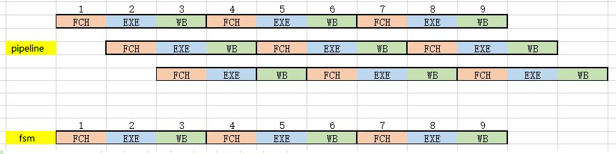
Figure 3 Comparison of pipeline state and state machine state in the same clock cycle
For pipeline:
- Clock Cycle 1: FCH, Instruction Fetch, ADDI
- Clock cycle 2: EXE & FCH, execute ADDI& get command ADDI
- Clock Cycle 3: WB & EXE & FCH, write result of X0+0 to a5 & execute ADDI & fetch instruction SB
- Clock cycle 4: FCH & WB & EXE, fetch instruction ADDI & write result of X0 +0 to s0 & execute SB
- …
Although for each instruction (such as 2 ADDI and SB), they still take 3 clock cycles to complete, in the same clock cycle, 3 instructions will be executed simultaneously. Except for clock cycles 1 and 2, the pipeline is not completely filled, so the execution efficiency is not high, and other clock cycles execute 3 instructions at the same time. For the same time period from clock cycle 1 to clock cycle 12, the state machine executes 4 instructions, while the pipeline executes at least 10 instructions. A pipelined CPU is definitely more efficient than a state machine CPU when the clock speed is the same.
Pipelining in computer architecture is also known as data pipelining. It decomposes a repetitive process into several sub-processes, each of which runs in parallel with other sub-processes. Since this working method is very similar to a production line in a factory, it is called pipelining, i.e. multiple sub-processes are executed simultaneously.
The classic 5-stage pipeline includes:
- fetch instruction
- instruction decoder
- execution
- memory access
- writeback.
FII RISC-V combines instruction decoding and execution, memory access, and write-back to form a 3-stage pipeline:
- Instruction Fetch (FCH)
- Execute (EXE)
- Write Back (WB).
3. Pipeline classification
Figure 4 shows a 3-stage pipeline. According to the execution order, pipelines can be divided into sequential pipelines and out-of-order pipelines. If a pipeline has feedback, it is defined as a nonlinear pipeline. In contrast, if the data in the pipeline flows from the first stage to the last stage, it is a linear pipeline. The pipeline has different stages, up to 31 stages (hyper pipelined technology, super pipeline technology). The development and use of different pipeline CPUs is because the efficiency and main frequency of pipeline CPU instruction execution have been greatly improved under the same production process and the same clock.

Figure 4 RISCV 3-stage pipeline
4. Pipeline conflicts
Pipelined CPUs also pay a price for high performance, for example, their logic is generally more complex than state machine logic. In addition, pipelined CPUs mainly generate three kinds of conflicts: data conflicts, structure conflicts, and control conflicts.
- data conflict
Data hazards occur when instructions at different stages of the pipeline exhibit data dependencies. For example, in Figure 5, instruction 2 is dependent on instruction 1, and s0 is both the result of instruction 1 and the addend in instruction 2. When instruction 1 wrote the result back to the register, instruction 2 was executed with the incorrect s0 value that was not updated. The solution is to bypass the value, which means pass the value of s0 from the result of instruction 1 to instruction 2 directly before writing back.
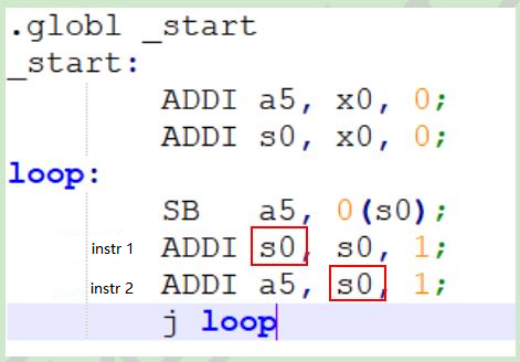
Figure 5 Data conflict
- structural conflict
A structural conflict occurs when two or more instructions in a pipeline require the same resource. For example, when an instruction is fetched from a memory block, at the same time another instruction is being written back to the memory block. The solution is to add a pipeline bubble (nop, no-op) before subsequent instructions, or to increase the available hardware resources.

Figure 6 Structural conflict
- control conflict
A control conflict occurs when the pipeline makes a bad decision about a branch prediction, so instructions that have been introduced into the pipeline must be discarded. For example, in Figure 7, when j loop is executed, the instruction immediately following it has been fetched. However, the PC (Program Counter) will jump to the loop label instead of pointing to the fetched instruction. In this case, the pipeline will execute the already fetched instruction as a nop (no operation).

Figure 7 Control conflict
