This article talks about the standard properties in device tree nodes.
For related subjects, please refer to the SOC Table of Contents.
Nodes consist of many different properties and different devices need different properties; the user can also create custom properties. Aside from the user’s custom properties, many other properties are standard properties which are used by countless Linux peripheral drivers. The most commonly used standard properties are as follows:
compatible
The value of compatible can be either a string of a list of strings, which most commonly has the format of <manufacturer>,<model>. You may choose to use a different format, but this is the standard format that the majority use for unity and compatibility. An example is as follows:
compatible = “manufacturer1,model1”,“manufacturer2,model2”;
The compatible property is used to associate devices with drivers: the device would first search the Linux kernel with the first compatible value (ie. manufacturer1, model1) to see if there are any drivers that match; if it fails to find any matches, it will move on to search using the second compatible value (ie. manufacturer2, model2), all the way until it finds a match or it fails after searching the entire Linux kernel.
Driver files usually have a 0F match table, where it stores some values of compatible. If any of the match table values is the same as the value of compatible in the device tree node, then it means the device can use the driver. An example is the driver file xilinx_uartps.c in /drivers/tty/serial/.
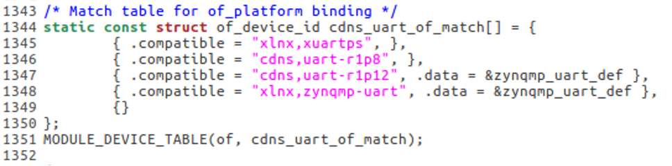
We can see that the match table for xilinx_uartps.c consists of 4 match values: “xlnx,xuartps”, “cdns,uart-r1p8”, “cdns,uart-r1p12”, and “xlnx,zynqmp-uart”. If any device tree node has matching compatible property values, the node would successfully pair with the driver file.
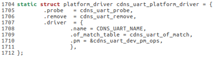
The above section of code sets up the 0F match table for platform_driver, mainly in line 1709, where .of_match_table is set as cdns_uart_of_match.
model
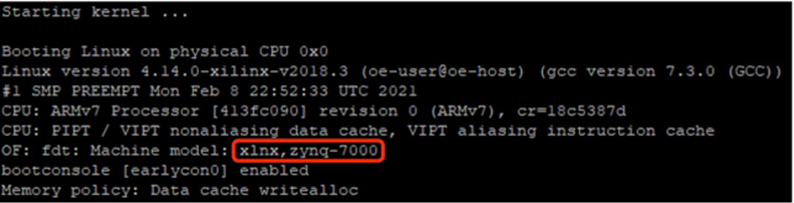
The model property is a string that specifies the device model and is typically defined in the root node. The purpose mainly being to help describe the device, and the string will be printed when the kernel is parsing the device tree.
For example, if we have the model value set in the system-top.dts file as follows, it would display the set string as the model. Note that chosen, aliases, and memory is all omitted for this example.
/dts-v1/;
#include “zynq-7000.dtsi”
#include “pl.dtsi”
#include “pew.dtsi”
/{
         model = “xlnx,zynq-7000”;
         chosen{
                 ...
         };
         aliases{
                 ...
         };
         memory{
                 ...
         };
};
status
The status property is used to mark the status of the device and can be used to disable or enable devices. There are four options to choose from when setting the value of status:
okay Shows that the device is operable and enables the device.
disabled Shows that the device is not currently operable but can be enabled.
fail Shows that the device is inoperable due to detected errors and is unlikely to be enabled.
fail-[error] Has the same meaning as fail but includes the error, where [error] is the detected error.
#address-cells and #size-cells
These two properties are all 32-bit unsigned integers and can be used in any device node with child nodes, as it is used to describe the address information of child directories.
#address-cells is used to describe the number of cells of the initial address in the address table used to describe the properties of the “reg” child node.
#size-cells is used to describe the number of cells of the address length in the address table used to describe the properties of the “reg” child node.
Both properties show how child nodes should write values of the reg property. The reg property is typically related to addresses, mainly being the starting address and the length of the address. Using these two parameters the reg property can describe a continuous address section. The format is as follows:
reg = <address1 length1 address2 length2 address3 length3 ...>
Note that each address and length represent an address section, and #address-cells defines the length of address while #size-cells defines the length of length. See example below:
 &qspi{
         #address-cells = <1>;
         #size-cells = <0>;
         flash0:flash@0{
                 compatible = “n25q512a”,“micron,m25p80”;
                 reg = <0x0>;
                 #address-cells = <1>;
                 #size-cells = <1>;
                 spi-max-frequency = <50000000>;
                 partition@0x00000000{
                         label = “boot”;
                         reg = <0x00000000 0x00500000>;
                 };
                 partition@0x00500000{
                         label = “bootenv”;
                         reg = <0x00520000 0x00a80000>;
                 };
                 partition@0x00520000{
                         label = “kernel”;
                         reg = <0x00520000 0x00a80000>;
                 };
                 partition@0x00fa0000{
                         label = “spare”;
                         reg = <0x00fa0000 ox00000000>;
                 };
         };
 };
Note how at the start, the node qspi’s #address-cells is <1>, and #size-cells is <0>. This means that the child node reg’s starting address is expressed using 32-bit data. On line 6 we see that the child node flash0:flash@0 has reg set as <0>. Because the parent node set #address-cells as <1> and #size-cells as <0>, address is thus 0 and doesn’t have a length value. This is equivalent to setting the starting address but not the address length.
On lines 7 and 8 the node flash0:flash@0 has #address-cells set as <1> and #size-cells as <1>. Meaning that the child nodes of flash0:flash@0 will have starting address and address lengths of 1.
reg
As shown in the previous section, reg typically has the parameters in pairs of address and length. reg is typically used to describe device addresses and information on resources, mainly with regards to peripheral registers and flash device partition information. An example is lines 174 – 181 from the zynq-7000.dts file in /arch/arm/boot/dts/:
  uart0:serial@e00000000{
         compatible = “xlnx,xuartps”,“cdns,uart-r1p8”;
         status = “disabled”;
         clocks = <&clkc 23>,<&clkc 40>;
         clock-names = “uart_clk”,“pclk”;
         reg = <0xE0000000 0x1000>;
         interrupts = <0 27 4>;
  };
The above section of code is the node uart0, which describes related information with regards to ZYNQ’s PS port’s UART0. The main focal is the 3rd last line’s definition of reg, which sets its address to 0xE0000000 and length to 0x1000. The start address 0xE0000000 is the starting address of ZYNQ’s UART0 register.
device_type
device_type usually has a string value to indicate the node type. Although this isn’t used frequently, it is most often used in nodes that deal with cpus or memory. An example is the cpu0 and cpu1 node in zynq-7000.dtsi.
cpu0:cpu@0{
compatible = “arm,cortex-a9”;
device_type = “cpu”;
reg = <0>;
clocks = <&clkc 3>;
clock-latency = <1000>;
cpu0-supply = <®ulator_vccpint>;
operating-points = <
/* kHz uV */
666667 1000000
333334 1000000
>;
};
cpu1:cpu@1{
compatible = “arm,cortex-a9”;
device_type = “cpu”;
reg = <1>;
clocks = <&clkc 3>;
};
Note how the device_type is set as cpu.
ranges
ranges is an address conversion table, where each element is a child directory, parent directory, and mapping of the size of the child directory. The value of ranges can be either left blank or set as a digital matrix using the following format: (child-bus-address, parent-bus-address, length). The length of the parent and child directories in the mapping table are defined by the #address-cells in the node that ranges is in, as well as the #address-cells in the parent node of ranges. On the other hand, the length of the child directory space is determined by the #address-cells in the node that ranges is in.
child-bus-address
- The physical address of the child bus address, where its length is determined by the #address-cells in the ranges node.
parent-bus-address
- The physical address of the parent bus address, where its length is determined by the #address-cells in the parent node of the ranges node.
length
- The length of the child directory, where its length is determined by the #address-cells in the node that ranges is in.
Note that if the value of ranges is left blank, it means the child directory is the same as the parent directory, and mapping is not necessary. If not left blank, it would look something like this:
  soc{
         compatible = “simple-bus”;
         #address-cells = <1>;
         #size-cells = <1>;
         ranges = <0x0 0xe0000000 0x00100000>;

         serial{
                 device_type = “serial”;
                 compatible = “ns16550”;
                 reg = <0x4600 0x100>;
                 clock-frequency = <0>;
                 interrupts = <0xA 0x8>;
                 interrupt-parent = <&ipic>;
         };
  };
Note that ranges in SoC sets the address range as 0x00100000 (1024KB), where the child directory starts at 0x0 and the parent directory starts at 0xe0000000.
serial is the serial device node, where reg specifies the starting address for the serial device as 0x4600 with a length of 0x100. After address conversion, the serial device can read and write from 0xe0004600 (0xe0004600 = 0x4600 + 0xe0000000).
